Reinforced Soil Walls - Concept
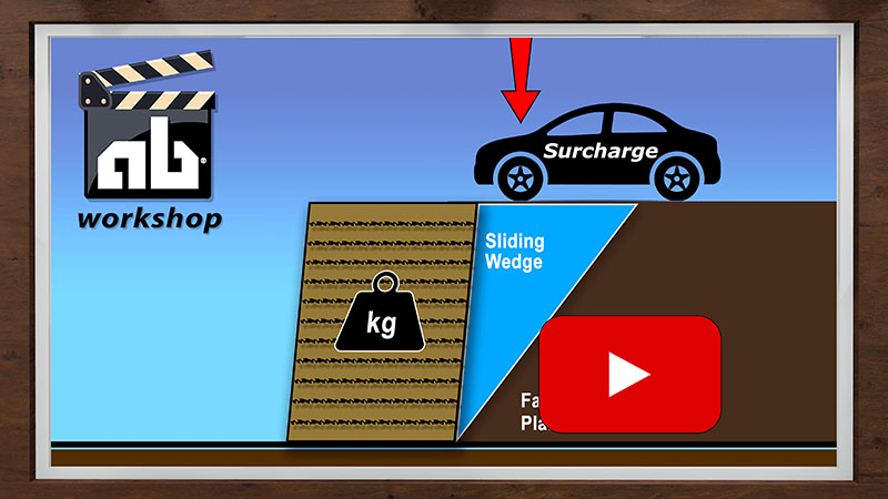
Video: How Does a Retaining Wall
Work
The Great Wall of China, dating back some 2,200 years, was built as a double sided retaining wall. The soil between the two walls was a mixture of clay and gravel reinforced with Tamarisk branches. Allan Block retaining walls employ “old technology with new materials.”
When retaining wall heights exceed those listed in the gravity wall chart, geogrid can be added to provide a stable retaining wall condition. Layers of geogrid inserted between the blocks and extending behind the retaining wall interlock with the surrounding soil to create a cohesive soil mass. This mass uses its own weight and internal shear strength to resist both the sliding and the overturning pressures from the soil being retained. The wall rock in the Allan Block cores provide a positive connection between the layers of geogrid and the Allan Block retaining wall, locking the two systems together. The reinforced soil mass becomes the structure and the Allan Block retaining wall becomes the facing. The specific location and embedment length of the grid layers depends upon the site conditions, wall heights and Long-Term Allowable Design Strength of the grid being used. See the approved plans for exact geogrid locations or consult with a local engineer.
Geogrids

Geogrid
Geogrids are flexible, synthetic meshes which are manufactured specifically for slope stabilization and earth retention. These “grids” are available in a variety of materials, sizes and strengths. They can be made of high tensile strength plastics or woven polyester yarns and are typically packaged at the factory in rolls. The grids are rated by Long-Term Allowable Design Strength (LTADS) with values ranging from 500 to 4,000 pounds per linear foot (7.3 kN/m to 58.4 kN/m). More information on types of geogrid.
Reference: Allan Block Engineering Manual
Positive Interlock
Positive Interlock
Positive Interlock
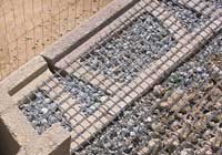
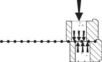
Allan Block’s gravel filled hollow core provides a multi-point interlock with the grid. As retaining wall heights increase, our exclusive “Rock-Lock” connection, combined with the weight of the wall blocks, provides the best block-to-grid interlock of any system on the market. See the tech sheets on connection testing or the Seismic Testing Executive Summary for testing results on the “Rock-Lock” connection. Connection strength testing has been done with our grid manufacturers for results see the AB Spec Book or AB Engineering Manual.
Reference: Allan Block Engineering Manual,Allan Block Spec Book, Allan Block Seismic Testing Executive Summary, ASTM D6638 Standard Test Method for Determining Connection Strength between Geosynthetic
External Stability
External stability exists when the entire wall system - the Allan Block facing units and the reinforced soil mass - act as a coherent structure to satisfy standard gravity wall analysis. Proper retaining wall design must satisfy all four of the following considerations.
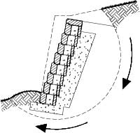
Global Stability
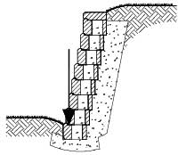
Bearing Capacity
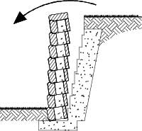
Overturning
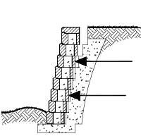
Sliding
Internal Stability
Internal stability is the ability of the reinforcement combined with the internal strength of the soil to hold the soil mass together and work as a single unit
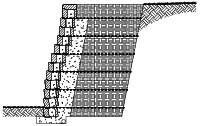
Bulging
Bulging occurs when horizontal forces between the geogrid layers causes localized rotation of the retaining wall.
Increase number of grid layers
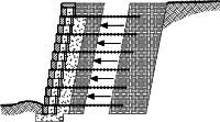
Pullout
Pullout results when grid layers are not embedded a sufficient distance beyond the failure plane.
Increase embedment length
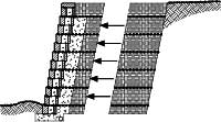
Grid Rupture
Rupture occurs when excessive forces exceed the ultimate tensile strength of the geogrid.
Increase grid strength or the number of grid layers
Internal Compound Stability
Slip plane that runs through the retained and reinforced soil and wall facing.
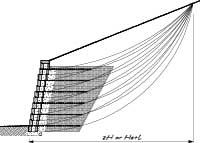
Internal Compound
Internal Compound instability occurs when a slip arc passes through retained soil, reinforced soil, and facing.
Increase length, strength, or decrease spacing of grid, use select infill material
Reference: Allan Block Engineering Manual, ASTM D6916 Standard Test Method for Determining the Shear Strength between Segmental Concrete Units, Task Force 27, In-Situ Soil Improvement Techniques, “Design Guidelines for Use of Extensible Reinforcements for Mechanically Stabilized Earth Walls in Permanent Applications,” Joint Committee of AASHTO-AGC-ARTBA, AASHTO, Washington, DC (1990)
Design Considerations
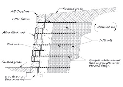
AB Geogrid Retaining Wall Typical Section
- Grid strength Select the right strength grid for the job. Choose LTADS grids from 500 lb/ft to 4000 lb/ft (7.3 kN/m to 58.4 kN/m).
- Embedment length Grid length must extend far enough behind the wall to create a sufficient reinforced gravity mass. Typically a minimum of 60% of total wall height.
- Number of layers Install enough layers to adequately increase the internal strength of the soil mass and handle all applied loads.
- Spacing between layers Grid layers must be correctly spaced to distribute internal forces. Typically spaced on 16 in. (405 mm) centers.
- Connection strength Block and geogrid must work together to resist internal forces.

