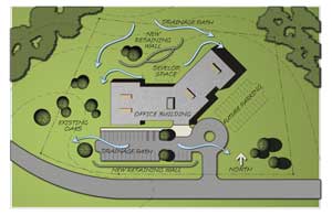
Plan
Develop an accurate understanding of the jobsite before beginning any design, engineering, or construction on a project.
Site Geometry
Develop an accurate plan of existing physical features. Observe the soil type and condition, site geometry at the retaining wall location and immediate surroundings. Note the natural drainage patterns. Identify all physical features surrounding the proposed retaining wall location. Note key elevations, lot lines, utilities, structures, vegetation, etc. Conditions above and behind the wall will determine how high the retaining wall can go before reinforcement is needed.
Soils
The soils used below and behind the wall are a critical part of the total retaining wall structure.
Understanding the properties and characteristics of soils is key to building better walls. Different soil types will dictate the amount of time needed for compaction, the amount of reinforcement required, and potentially the cost of the retaining wall.
Check the on-site soils carefully before beginning, and get a written identification of the soil type. A soils report from a local engineer will be required before a design and/or permit is issued for most retaining walls above 4 ft. (1.2 m). See the Soils Chart for a general classification of soils.
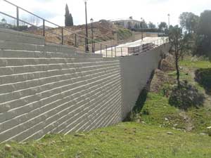
AB Collection retaining wall
- Soil conditions behind and below each retaining wall have a direct effect on the strength needed in that retaining wall. The pressure from behind the wall will vary substantially depending on the soil type. In general, a wall built in clay soils will require more reinforcement than a wall of the same height built in free draining sand or gravel soils.
- Check the soil type and conditions at the base of each wall for adequate bearing pressure. The soil below a wall needs to be strong enough to support the weight of the wall resting on it. When moisture is present, extra precautions may be required to provide a stable base.
- If the soils at the base of the wall have been disturbed - i.e. excavated and replaced - it is imperative that these soils are properly compacted before construction begins. It may be necessary to remove poorly compacted or soft, wet organic soils at the base and replace them with stable, well compacted soils prior to wall construction.
Soil Selection
If the on-site soils are of a very low quality, you should remove and replace them with better backfill material in the reinforced zone and the foundation area. The cost of removal will be offset by reduced reinforcement, faster compaction, and better long-term performance.
In the reinforced zone, the type of soil used will determine the amount of grid reinforcement needed. Heavy clays and organic soils are both unsuitable in the reinforced zone. Generally, any soil with a friction angle lower than 27° (Ref) or a plasticity index (PI) of greater than 20 should be removed and replaced. Soils with friction angles between 27° (Ref) and 31° (Ref) will require additional care, and attention to water management when placed and compacted. This will include extra inspections by an on-site engineer. See the Soils Chart for information on friction angles of soil
You must use infill soils that meet or exceed those specified in the engineered specifications and drawings. Have the soils tested before placing and compacting.
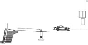
Parking lot drainage
Water Management
Make a careful observation of the general drainage patterns at the site. Note the amount of area above the wall which will shed surface runoff toward the wall. Note the type of surface (i.e., paved surfaces, sodded areas, etc.) to determine the water flow and volume. Note any concentrated sources of water flow such as runoff from parking lots, roof drains and scuppers, drainage swales, creek beds, ground water, etc. Learn more about Water Management.
Grading
Develop a grading plan that routes water around the retaining walls as much as the site will allow. Provide swales above and below the retaining wall as required to accommodate water movement. Divert sources of concentrated water flow from the wall. Retaining wall designs must prevent the pooling of water above or below the wall.
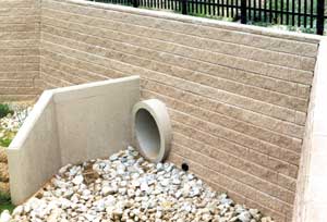
Retaining wall drainage
Drainage
Proper drainage planning considers water flow and volume above, below, and behind the retaining wall.
- Most Allan Block gravity walls (lower unreinforced walls) will drain adequately on their own.
- If a large area sheds water to the wall (i.e., parking lot), added drainage will be necessary.
- Concentrated sources of water must be planned for and managed.
- Reinforced walls will need added drainage for the backfill zone and the wall base.
- Major wall structures, roadway and municipal projects, and walls built in extreme rainfall or wet environments will need a thorough hydrology analysis prior to construction
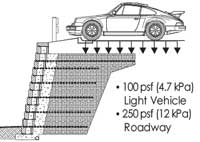
Retaining wall surcharges
Surcharges
Any added weight above the wall is called a surcharge. Parking lots, swimming pools, and driveways are common surcharges. Light duty surcharges are designed at 100 psf (4.7 kPa). Heavier commercial surcharges (like trucks), run 250 psf (12 kPa) and up. More concentrated line loads may also be a factor (such as building foundations). Engineering is required in each situation.
Reference: Allan Block Engineering Manual
Slopes
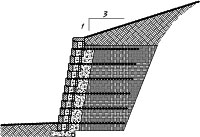
Retaining wall with slope above
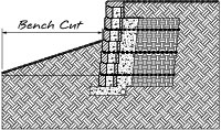
Retaining wall slope below wall
Slopes are measured run to rise. A three-to-one slope goes back 3 and up 1.
Slopes Above
Slopes above the wall add more pressure and will require more mass to resist movement. Engineering is required.
Slopes Below
Slopes below the wall may create an unstable foundation. Check with local building codes for length of bench that may be required. Engineering is required.
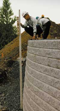
Retaining wall setback (story pole)
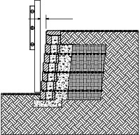
Retaining wall setback
Setback
The amount the wall leans into the hill is called setback. AB units come in multiple setbacks. Bigger setbacks provide better leverage and require less reinforcement. For taller walls use a story pole and level to check for proper setback. Setbacks increase when walls are built with radii. Comply with construction tolerances which are found in the AB Spec Book or approved construction plans.
Note: Walls designed with a 12° (Ref) setback require more space than 6° (Ref) or 3° (Ref) systems, but will be more stable. You may give up ground, but the final factors of safety are higher.
Global Stability
Global stability is an engineering analysis of the overall balance of a slope or hillside. Walls built on hillsides may affect this balance and stability. Cuts into a hillside will steepen the effective slope and shift the balance of the hill, thereby reducing stability. Walls built on top of slopes have the same effect. Engineering is required.
What to consider when assessing global stability:
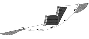
Retaining wall global stability
- Surcharges / Terraced Walls
- Slopes
- Soil Properties
- Water
Reference: Allan Block Engineering Manual, Terzaghi, K, and Peck, R B, Soil Mechanics in Engineering Practice, John Wiley and Sons, Inc., New York, NY (1967)


