Designing Your Project: Sections
Defining your Soils
- The first step in designing a section is to define the soil parameters. The user should input the site-specific soil parameter for their project. These parameters can be defined per section and will be saved with the design file.
- Multiple soil types can be used for infill and retained soil zones. If multiple soil types are to be used in the project, click the check box for multiple soils. This will bring up the next tab where multiple soil types can be entered.
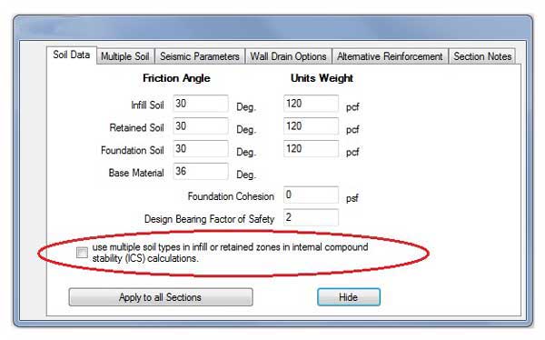
For more information on the Multiple Soils, Seismic Parameters,Wall Drain Options, Alternative Reinforcement and Section Notes, see Appendix D.
Designing Sections
- The program will start the section designs with the tallest section. When you complete your first section use the up or down arrow to move to your next section.
- The section is defined by its position from the Panels screen and therefore the information in the Section Height is already defined.
- The Number of Buried Blocks section is defined by the height of the section. In a design with a defined elevation profile the number of buried blocks is defined by its position from the Panels screen. In a zero section the user has the ability to specify the Number of Buried Blocks directly.
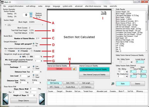
- The program automatically defaults your project to be a geogrid reinforced wall design. If you want to design your wall as a gravity wall or No Fines Concrete wall, you will need to choose No to the question; Design with Geogrid?
- Geogrid layers placed at a 2-course spacing is the default setting. This can be modified by the designer to fit the site-specific design.
- The default value for geogrid lengths is equal to 60% of the wall height. The designer can choose to modify these defaults to fit their site-specific designs.
- The minimum length of geogrid can also be modified to suit the projects requirements.
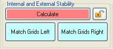
- Click Calculate to view your section. If you have already designed a section, such as, Section 2, when designing Section 1 you can use the Match Grids Right button to place the grid layer in Section 1 at the same relative position as in Section 2. The same goes for Section 3, but use the Match Grids Left button. Having the grid layers on the same course from the start to the end of a wall is helpful during construction.
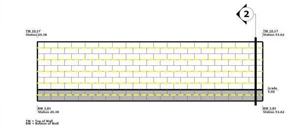
- There is a toggle in the section design screen that allows a panel view pop up window to be displayed or not. The panel view pop up display shows the cross section location as well as the panel elevation. The window also displays the top of wall (TW), bottom of wall (BW) elevations and stationing of each individual step up or step down location.
For the NFC / Gravity and Double Block buttons these are Complex Composite Structures, see Appendix F: Complex Composite Structures for additional discussion.
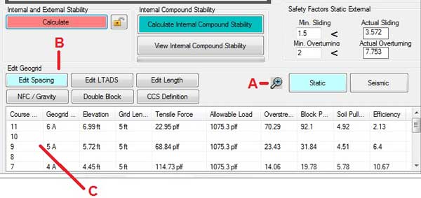
Editing Geogrid
Internal Stability Safety Factors in the Edit Geogrid section include Grid Overstress, Grid Pullout from Soil and Grid Pullout of Block.
Safety Factors all must be over 1.5 for static and 1.1 for seismic designs. The designer can change the safety factors by changing the grid spacing, grid strength, grid depth or the grid type.
Edit Spacing
Edit Spacing has an effect on all three internal safety factors.
- To view a larger internal stability screen, click on the (+) magnifying glass. Click the (-) magnifying glass to minimize this screen.
- Edit Spacing allows the designer to reposition grid layers.
- To remove a layer, click the course number that contains a layer of grid. To put a layer somewhere else, click the desired course number that does not contain a layer of grid
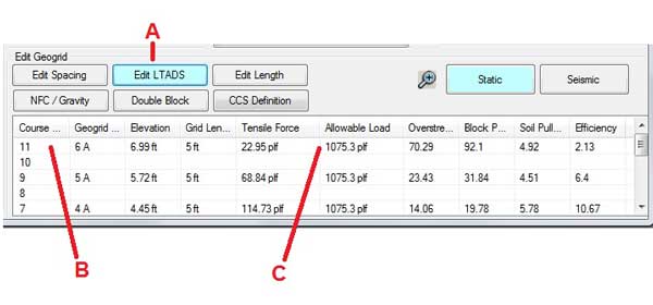
Edit Long Term Allowable Design Strength (LTADS)
Edit LTADS mainly effects grid Overstress calculation, but will also change the other internal stability factors because the actual grid test results will be used for each calculation.
- Edit Long Term Allowable Design Strength (LTADS) of the geogrid layer.
- Click the course number to increase that layer of grid to the B-Type grid and click it again to change it to the C-Type grid. Click it again and it returns to the A-Type grid.
- The grid strength is shown in the Allowable load cell of the table.
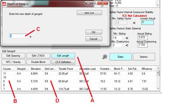
Edit Depth
Edit Depth effects pullout of soil calculations.
- Editing the depth of geogrid embedment.
- Click the course number of the layer you wish to change.
- Enter the new length in the pop-up box and click OK.
- The revised grid length appears in the grid length cell.
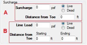
Surcharges
AB Walls allows the designer to use two types of surcharges, a distributed surcharge or a line load.
- The Surcharge allows the designer to apply a continuous surcharge from a starting position they define, and continue without end.
- The Line Load surcharge can also be live or dead load but, the starting and ending positions can be defined by the designer.
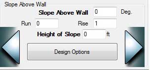
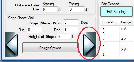
Slopes Above Walls
Enter the Slope above Wall in Degrees or by entering the Rise and Run.
For broken back slopes, or slopes that are not infinite, a height of slope box is included. Input the height above the top of wall at which the slope levels out and the program will adjust the calculations accordingly. The height of the slope is measured from the top of the wall to the top of the slope.
For more information on steep slopes, see the Trail Wedge Design Method in Appendix E.
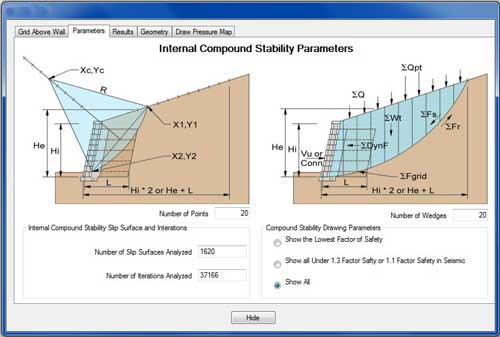
Calculate Internal Compound Stability
For an in depth discussion on ICS see chapter 6 in the AB Engineering Manual.
- Calculate ICS - After the software runs the ICS calculations, the ICS Parameters screen appears. On this screen, the user can see the number if slip surfaces and the number of iteration this section required to determine the minimum ICS safety factors for each block course.
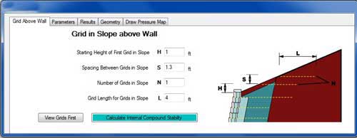
ICS - Geogrid in the Slope Above
- If the section has a slope above the wall, the designer will be asked if they want to put geogrid in the slope above. If they click yes, they can enter the geometry of the added geogrid layers. The geogrid that is used is always Type-A.
- Adding geogrid to the slope above can greatly improve the ICS safety factors by adding stability to the slope. This also will benefit the internal safety factors for the top wall grid by decreasing the area that one grid layer reinforces.
NOTE: ICS does not take the place of a global stability analysis.
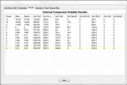
ICS - Results
The results tab displays the detailed ICS calculation results for all courses of the wall.
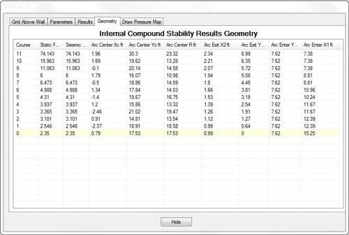
ICS - Geometry
The results tab displays the detailed ICS calculation geometries for the worst case slip arc for all courses of the wall.
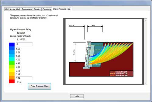
ICS - Draw Pressure Map
- The pressure map shows the distribution of the internal compound stability slip arc factors of safety.
- Factor of safety range can be modified to refine pressure display.
Clicking the arrow pointing to the right will move you to the Quantities Worksheet screen.
After all the sections have been designed, it is recommended to confirm the geogrid layout by clicking the arrow pointing to the left, taking you back to the Panel View.