Appendix F: Complex Composite Structures
How to Design a Complex Composite Structure
Any cross section can be analyzed as a Complex Composite Structure. In order to analyze a Complex Composite Structure a user must:
Select the section that will be a Complex Composite Structure while in the Section Design Screen.
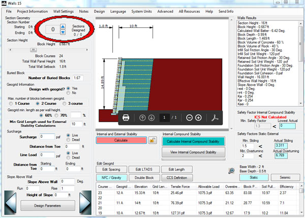
The next step is to modify the section so that it is not a typical design section. This will cause the program to start evaluating that section as a Complex Composite Structure. This can be achieved using any one of the following methods.
- Gravity wall above geogrid reinforced soil mass
- Simple Gravity Wall
- Double Block Gravity Wall
- Fieldstone Long Anchoring Units (LAU) Gravity Wall
- Two Different Reinforced Masses
- Longer Grid on Top
- Double Block Gravity Wall
- Shorter Grid on Top
- No Fines Concrete (NFC) and Geogrid Reinforced Soil Mass
- NFC above Grid Below
- NFC Bottom Grid Above
- NFC Bottom Gravity Wall Above
- No Fines Concrete with Two Different Mass Depths
Method 1
- Gravity wall above geogrid reinforced soil mass
- Simple Gravity Wall
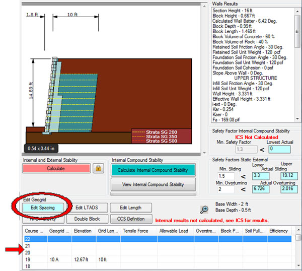
- Use the Edit Spacing button to start removing layers of geogrid at the top of the wall.
- This is done by clicking on the Edit Spacing button.
- Then by clicking the individual courses in the internal results table to modify the geogrid configuration.
- This causes the program to analyze the top of the wall as a simple gravity wall above a geogrid reinforced soil mass.
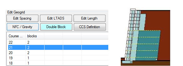
- Double Block Gravity Wall
- After the composite mass is created from (a) click the Double Block button.
- Click the individual courses in the internal results table to modify the blocks from Short Anchoring Units (SAU) to a LAU gravity wall.
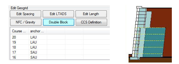
- Fieldstone Long Anchoring Units (LAU) Gravity Wall
- After the composite mass is created from (a) click the Double Block button.
- Click the individual courses in the internal results table to modify the blocks from Short Anchoring Units (SAU) to a LAU gravity wall.
- Simple Gravity Wall
Method 2
- Two Different Reinforced Masses
- Longer Grid on Top
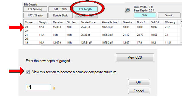
- Edit two or more consecutive geogrid layer lengths at the top of the wall to be longer than the layers below them.
- This is done by clicking on the Edit Length button.
- Then clicking the individual courses in the internal results table to modify the individual geogrid lengths.
- When editing the length for the second geogrid check the “Allow this section to become a Complex Composite Structure”.
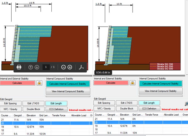
- Shorter Grid on Top
- Edit two or more consecutive geogrid layer lengths at the top of the wall to be shorter than the layers below them.
- This is done by clicking on the Edit Length button
- Then clicking the individual courses in the internal results table to modify the individual geogrid lengths.
- When editing the length for the second geogrid check the “Allow this section to become a Complex Composite Structure”
- Longer Grid on Top
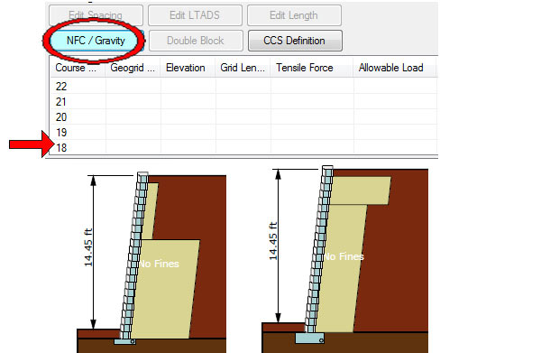
Method 3
- No Fines Concrete (NFC) and Geogrid Reinforced Soil Mass
- NFC above, Grid Below
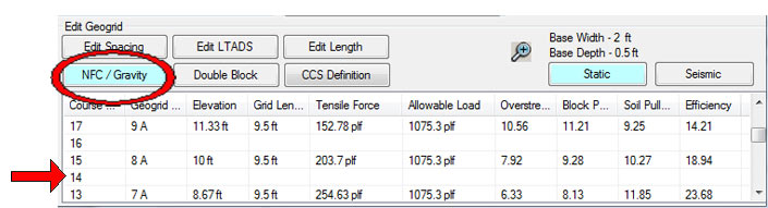
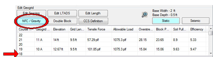
- Use the NFC / Gravity button to use either No Fines Concrete for a portion of the cross section
- This is done by clicking on the NFC / Gravity button
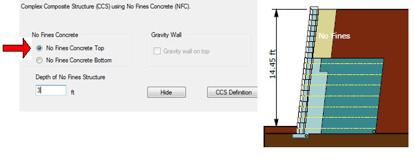
- Then clicking the course in the internal results table where the two structures will differentiate.
- This will bring a pop up window where the user can select whether they want a No-Fines Concrete structure on top and a geogrid reinforced soil mass structure below and specify a depth to the No-Fines structure.
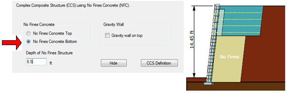
- NFC Bottom Grid Above
- Use the NFC / Gravity button to use either No Fines Concrete for a portion of the cross section.
- This is done by clicking on the NFC / Gravity button
- Then clicking the course in the internal results table where the two structures will differentiate.
- This will bring a pop up window where the user can select whether they want a No Fines Concrete structure on the bottom and a geogrid reinforced soil mass structure above and specify a depth to the No-Fines structure.
- NFC bottom Gravity Wall Above
- Use the NFC / Gravity button to use either No Fines Concrete for a portion of the cross section.
- This is done by clicking on the NFC / Gravity button
- Then clicking the course in the internal results table where the two structures will differentiate.
- This will bring a pop up window where the user can select whether they want a No Fines Concrete structure on the bottom and a gravity wall structure above and specify a depth to the No-Fines structure
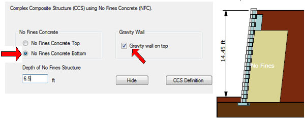
- For the case of a gravity wall above a No Fines mass below, once again the user has the option to select either a Double Block gravity wall or a Long Anchoring Unit (LAU) if using the AB Fieldstone product as explained in Method 1 above.
- NFC above, Grid Below
Method 4
- No Fines Concrete (NFC) and Geogrid Reinforced Soil Mass
- This type of structure can be achieved by starting with a full No Fines Concrete design using the following steps.
- Start by clicking on the Design Parameters button in the lower left corner of the screen.
- Then select the Design Options Tab.
- Select the Design with No Fines Concrete to Yes and specify a depth for the No Fines Concrete mass.
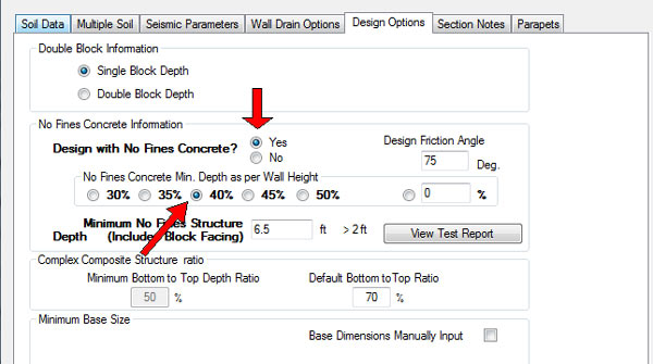
- After clicking Hide click the Calculate button. Initially the section will be designed as a standard No Fines Concrete mass.
- To finish the design as a Complex Composite NFC Structure click the NFC / Gravity button and then select the structure configuration as shown in Method 3.
- This type of structure can be achieved by starting with a full No Fines Concrete design using the following steps.