Designing Your Project: Plan View
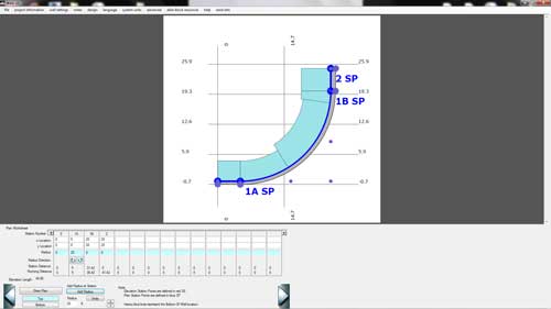
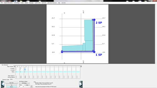
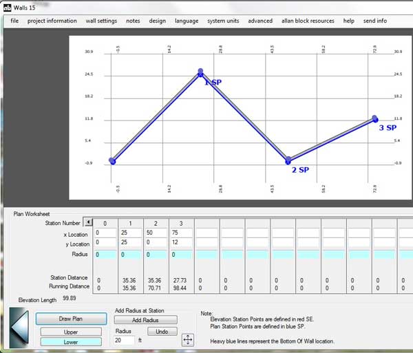
The plan view works on an x-y coordinate system.
Start by choosing either the top or bottom wall to be held to the site plan alignment.
- Enter the x-y coordinates into the table any time the wall changes direction and for the hard points of your wall such as the start, inside and outside corners and the end.
**IGNORE all radii as you will input them after you have your basic plan input. - The user has the choice of having the points represent the top of the wall or the bottom of the wall.
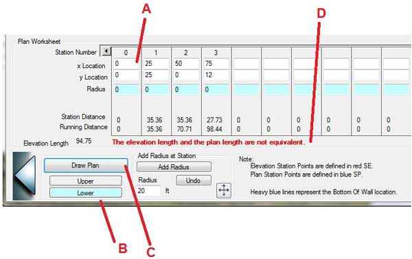
- When the table is complete, click the Draw Plan button
- If the plan view length does not match the elevation view length then the user receives a notification message.
Drawing A Radius Between Two Defined Points:
- If you have a straight wall segment you want to change to a large radius. Input the desired radius in the cell below the first point and use the direction arrows to define the direction of the radius.
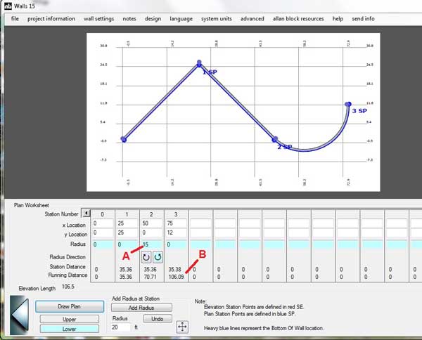
- Running distance on the plan should be close to total elevation length. If the numbers are substantially different, material quantities will vary greatly between calculations using the elevation and calculations using the plan. Modify the elevation or the plan as necessary. (See Items B & C in Appendix B for Advanced Chord Length Editing.)
For Advanced Plan Options, see Appendix B.
- If the user goes back to the plan view after designing all of the cross sections they will see that the program shows the geogrid layout for the wall. This is useful as the designer can visualize the geogrid layout to determine if any of the items for the site design will interfere with the geogrid layout.