Technical Newsletter
Issue 6
Project Information
Name: San Diego Jewish Academy
San Diego, California
Product: AB Rocks
Size: 70,000 ft² (6,500 m²)
50 ft (15.2 m) maximum height
Wall Builder: West Coast General
Allan Block Manufacturer:
Orco Block - Riverside, California
For more information on this project, check out the case study
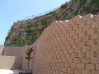
San Diego Jewish Academy Retaining Wall
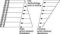
Old Methodology Prior To Testing
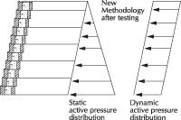
New Methodology After Testing: Active Pressure Distribution


Design retaining walls in both static and seismic conditions with AB Walls Design Software
A Dynamic Solution
Like the rest of Southern California, San Diego County has a number of active earthquake faults. In recent years there have been several earthquakes recorded within the Rose Canyon Fault Zone as it passes beneath the city. And when designing retaining walls in this seismic region, an additional dynamic load must be considered. Yet knowing this, it did not stop the construction of one of the tallest segmental retaining walls in the United States.
The San Diego Jewish Academy’s Carmel Valley Campus was in need of new facilities with their current rented spaces overcrowded and outdated. The 40 acre site, adjacent to Interstate 5 in Northern San Diego County, was just what the Academy was looking for. This hillside lot could have easily been overlooked, but Allan Block retaining walls with heights reaching 50 ft (15.2 m) enabled a beautiful, functional, and fast paced project to be completed.
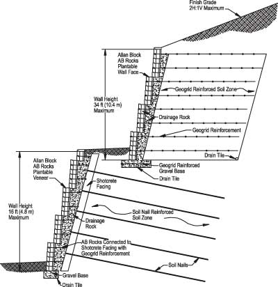
The south walls were cut walls with maximum heights of 50 ft (15.2 m) and the north walls were fill walls with maximum heights of 25 ft (7.6 m). Obviously, the design of the retaining walls required involvement from all engineering parties contracted for the project. There were many design factors that were considered including height, soil conditions, slopes, surcharges and, of course, seismic loading.
With minor seismic events happening daily throughout Southern California and even a 5.2 magnitude on the Richter scale happening in June of 2004, the walls have stood these seismic tests for more than 10 years – once again proving that Allan Block is a viable site solution for your project.
Seismic Loads and SRW's
The Segmental Retaining Wall (SRW) industry has evolved significantly over the last three decades, which is a given considering the industry did not exist 30 years ago. The SRW design evolution has been most dramatic relative to the incorporation of loads from seismic events. These changes were not precipitated as a result of poor performance.
On the contrary, design professionals saw exceptional performance on soil reinforced segmental retaining walls and reinforced slopes when they were exposed to seismic loading.* The first published seismic design methodology came from the NCMA (SRW Seismic Design Manual, 1st Edition, 1998). It suggested that the seismic loading be applied to the wall in the form of an inverted triangle, which focused most the load at the top of the wall. This greatly exaggerated the seismic forces when a slope was present above the wall. The Federal Highway Administration (FHWA) came along with a variation that also looked at the location of geogrid layers, which actually penalized the designer for concentrating grid layers near the top of the wall.
In 2004, a series of full-scale seismic tests were conducted by Prof. Hoe Ling (Columbia University) and Prof. Dov Leshchinsky(University of Delaware) as the principal investigators in cooperation with Columbia University, Allan Block Corp. and Huesker Inc.*
These full-scale tests not only demonstrate the superior performance of SRW’s under dynamic loading of 0.80 g horizontal and simultaneously 0.40 g vertical, but also helped to lead the way to a series of methodology changes across the industry. During the fullscale testing, it was clear that actual load distribution was not focused at the top of the wall as defined in the NCMA design manual nor was it dependant on where the reinforcement was placed as presented by the FHWA. Rather in each of the test structures, the additional load manifested itself in the form of a rectangular pressure distribution similar to what is applied from surcharges above the structure.
These findings triggered changes within the NCMA and FHWA methodologies resulting in new rectangular seismic pressure distributions for both, NCMA, 3rd Edition and the FHWA-NHI manual both published in the fall of 2009.
Translating what was learned in the testing to practical uses in the field
It was determined that the optimum configuration for a reinforced soil structure included lighter weight geogrids combined with a maximum grid spacing of 16 inches (400 mm) as opposed to stronger grids at greater spacings.
The tests also illustrated that minimum grid lengths of sixty percent (60%) of the height of the wall were adequate, but extending the top grid length to ninety percent (90%) of the height of the wall provided a bridge between the reinforced soil mass and the retained soil. This greatly reduced the soil cracking that occurred behind the reinforced mass when the grids were all truncated to the same length.
*For a more in depth discussion and copies of all references, see the Seismic Loads and Segmental Retaining Walls Tech Sheet.
Using AB Walls 10: Designing Slopes in Seismic Regions
AB Walls 10 seamlessly designs Allan Block retaining walls in both static and seismic conditions by simply entering the seismic coefficient for your site.
A slope above a wall steeper than the internal friction angle of the soil indicates the slope above the wall is not naturally stable. These slopes may require an engineered solution by reinforcing them with geogrid. AB Walls 10 will automatically adjust the slope to be less than the retained soil’s internal friction angle. An excepted practice to model the engineered slope is to simply add an equivalent live load surcharge above the wall for the remaining slope.
If the project location requires a seismic analysis, the Mononobe-Okabe (M-O) soil mechanics theory provides designers the seismic earth pressure coefficient to apply to their retaining wall. This equation becomes limited by its mathematics when low strength soils, steep slopes, and high seismic accelerations are combined. This may be translated to say that for specific combinations of slope angles, soil strength and seismic acceleration the project changes from a segmental retaining wall design to a slope stability problem.
For slopes that are planned to exceed the maximum allowable value, the M-O equation does not provide for accurate loading values and therefore does not accurately evaluate pseudo-static loading. We recommend consulting a geotechnical engineer for a more in depth analysis and possible solutions.
Confusion over Seismic Codes

In 2009 most of the United States adopted the International Building Code (IBC). For SRW designers,the IBC seismic code has been called confusing because it seemed to depart so much from the widely used UBC. In the UBC, the horizontal ground acceleration coefficient (Ao) was easily accessible in tables and maps and was widely used in SRW designs. ( i.e. NCMA’s SRWalls, Allan Block’s AB Walls and ADAMA’S AASHTO/MSEW) The question becomes, what IBC values should be used to replace Ao? In the IBC, where the Peak Ground Acceleration (PGA) replaces Ao, it is not well defined and does not clearly differentiate between building structures and soil reinforced structures. To help engineers determine site-specific seismic criteria the US Geological Survey(USGS) has a free downloadable program The user inputs a variety of site parameters and the program provides usable data including shake durations and acceleration values (PGA or in the program, Sa). The program does not however directly answer the acceleration question for a particular SRW project.
According to Daya Bettadapura of ABI Consultants in Irvine, CA, it becomes a question for the local geotechnical engineer that is reviewing the project. Prior to each project, it is important to have this conversation because geotechnical engineers will require a wide range of values. It is not uncommon to use PGA, 2/3 of PGA, 0.15g, 0.4g or something different, depending on where the project is located. With a range of usable values such as these, the confusion can be eliminated by involving your local geotechnical engineer.


