Technical Newsletter
Issue 3
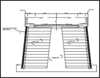
Two walls create the ramp that allows for traffic & pedestrians to flow underneath it
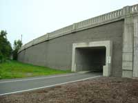
Project Information
Name:Herrick Street Bridge
Rensselaer, NY
Product:AB Classic
Certified Allan Block Contractor:Russ Reeves C. Engineer & Ryan-Biggs Assoc.
Allan Block Manufacturer:
Zappala Block - Rensselaer, NY
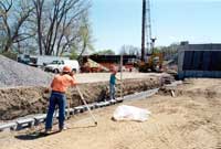
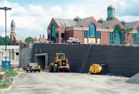
Tackle Design Hurdles with Knowledge
The city of Rensselaer needed a site solution that would not only be aesthetically pleasing, but would also create additional roadway access to one of the busiest rail stations in the state of New York. The design called for an off ramp bridge that would lead traffic from a major highway into the parking lot of the Rensselaer Rail Station.
The site plan called for two walls to create the ramp that would also allow for traffic and pedestrians to flow underneath it. Therefore, in addition to designing a ramp, the plan also called for a tunnel design.
The Allan Block manufacturer, Zappala Block, successfully proposed the Allan Block Retaining Wall System as the cost effective and aesthetically pleasing choice. The retaining wall design would also meet the high demands of the project including the stiff requirements and specifications of the American Association of State Highway and Transportation Officials (AASHTO).
Zappala Block worked with the engineer of record, Russ Reeves C. Eng., and the reviewing team of engineers at Ryan-Biggs Associates to make the project a triumphant one.
The cooperation and dedication of the many individuals involved in the project made the Herrick Street Bridge a success. To find out more about this Herrick Street Project and many others, check out the case studies here.
Consider these Details for Future Projects
For this project the greatest design hurdles came from a combination of a large surcharge and multiple soil conditions. Here are a few technical details to consider when working on similar projects:
- Surcharges - Vehicle traffic, paving materials, and an impact barrier were the factors considered as a surcharge. The added surcharge called for increased geogrid lengths compared to a typical retaining wall without a surcharge.
- Layout – It was vital that the survey crew was accurate when locating the starting course elevation and location. The start of the tunnel and radii along the wall all had to consider the wall batter or setback since the location at the top of the retaining wall was critical. Since two retaining walls were back-to-back, this became even more important to ensure the proper space for the ramp, sidewalks and railings.
- Tunnel Construction – A concrete collar was required around the entrances of the tunnel. Additionally, lightweight expanded shale was used to reduce the weight above the tunnel, which required more geogrid reinforcement, than the gravel backfill. Additional grid was also used where the tunnel and the retaining wall met to compensate for differential settlement.
Allan Block is a Key Contributor to the New CHMA Design Manual
This month, the Concrete Masonry & Hardscapes Association (CMHA) released their CMHA Design Manual for Segmental Retaining Walls 3rd Edition. This design manual updates the NCMA Design Manual for Segmental Retaining Walls 2nd Edition and combines it with the Segmental Retaining Walls – Seismic Design Manual and Segmental Retaining Wall Drainage Manual. Many key changes have occurred in the industry since the release of the 2nd Edition over 10 years ago, and to our liking this new manual finally defines many of the ideas Allan Block has had for years.
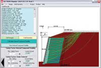
One of the key advancements in the industry was the inclusion of internal compound stability (ICS). Allan Block Corporation is acknowledged in this new manual as a key contributor to the development of the ICS analysis. Together with the NCMA and recognized industry leaders, we were able to develop calculations to model the conditions within the wall envelope using the Simplified Bishop Method of Slices. The wall geometry, soil parameters, geogrid reinforcement strength and spacing, facing stability from the geogrid connections, and facing stability from block shear strength are all fully considered in the analysis of ICS. ICS has been available in AB Walls Design Software since the fall of 2007 and you can see a complete discussion in Chapter 6 of the Allan Block Engineering Manual or in Chapter 8 of the new CMHA Design Manual.
To date Allan Block Corporation, together with Huesker Geosynthetics and Columbia University, is the only segmental retaining wall company to ever perform full-scale seismic testing on a Segmental Retaining Walls. The results of these tests were a huge step forward for the industry to actually understand what happens to a segmental retaining wall during a seismic event. The engineers and industry leaders behind the new edition of the CMHA Design Manual have acknowledged these tests as a critical part of the update. The industry has a better understanding of how the dynamic earth pressure is analyzed and revisions have been added to the new manual. Take a look at a copy of our Seismic Testing Executive Summary here.
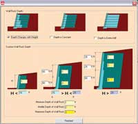
CMHA’s new design manual also discusses the rock placed in and directly behind the segmental retaining wall. While the CMHA describes it as drainage aggregate in the 2nd Edition, the 3rd Edition renames it as engineered gravel fill and denotes its primary function is to promote compaction and its secondary role is to provide a drainage path for incidental water that may enter the wall from above. Allan Block has described that material this way for many years and AB Walls Design Software takes this principle a step further by allowing the engineer to define the height and depth of wall rock behind the wall. The engineer can choose a varied depth, a constant depth, or the full depth of the infill zone.
Other Changes to the CMHA Design Manual Include: Section 3 of the manual suggests roles and responsibilities for the parties involved on the project. Having a site civil engineer, retaining wall engineer, and geotechnical engineer involved on a project can create the potential for issues to be overlooked because the roles are not clearly defined. By following these roles and responsibility guidelines, your project may run more smoothly and allow for a more successful project for the owner.
The manual also specifically discourages the design engineer or inspector from being contractually tied to the builder of the project. This is not in the best interest of the owner.It is recommended that the owner or an owner’s representative coordinate the design and inspection activities of the retaining wall. By having a direct contractual relationship between the designer and the owner, you are ensuring the designer is acting in the best interest of the owner.
Technical changes include:
- Deletion of the concept of hinge height
- The bulging calculation at the face of the wall has been replaced by ICS
- The serviceability requirements for connection strength between the SRW and geogrid have been eliminated.
- The product tolerances have been thoroughly explained and tightened beyond that described in ASTM 1372
- The CMHA design methodology is now allowing the vertical component of dead load to be used in calculation.
New AB Design Analysis Comparison Tool Released
As mentioned in the front article, the design of the Herrick Street Bridge retaining wall used the AASHTO design methodology. Even though there are numerous design methodologies used in the SRW industry, the underlying Allan Block unit does not change.
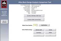
AB Walls Design Software is used by engineers around the world and in an effort to develop a better understanding of the different design methodologies used, Allan Block has created an easy to use Microsoft Excel based design comparison tool. This tool allows a wall designed in AB Walls 2007 to be compared to the output generated by other design methodologies. Currently this tool allows output from AB Walls 2007 to be compared to the new CMHA design methodology laid out in the new 3rd Edition, the CMMA Segmental Concrete Reinforced Soil Retaining walls for Australian Designs, and the ULS analysis for Italian designs. The AASHTO LRFD and British BBA BS8006 design comparisons will be available soon. In addition to the AASHTO and BBA design comparison, we will be adding additional design methodology comparisons to this tool as necessary. This comparison tool is available to engineers registered with AB Walls Design Software. To learn more about AB Walls Design Software, please use the update button in AB Walls for a link to the design comparison tool web page or call the Allan Block engineering department at 1-800-899-5309.
Helping You Go Green

Did you know that one of the LEED® credits for Materials and Resources is Regional Materials (SS Credit 5.1 and 5.2)? Projects earn extra credits for using products that are manufactured within a 500 mile radius of the project. Additionally, the raw materials used to manufacture the products must be within this same radius.
Allan Block has a vast network of manufacturers throughout North America to supply our concrete products efficiently. The majority of Allan Block projects installed today qualify for the regional materials credit. In fact, the featured project in this Newsletter was built within one block from our manufacturer, Zappala Block in Rensselaer, NY.
For a detailed description of how Allan Block products can help your project achieve LEED®credits check out our Green Opportunities.


