Technical Newsletter
Issue 28
AB Supports Multi-Use Sports Stadium at DePauw University
DePauw University recently completed a plan that focused on the addition of a multi-use sport stadium as well as practice fields. Around the stadium and practice fields were large grade changes that required the placement of several retaining walls. The university expected the walls to not only provide the highest level of structural soundness, but they demanded walls that enhanced their student population’s athletic field experience with favorable pedestrian access points that provided a high degree of aesthetics. The system that was chosen that met all their requirement was the Allan Block Ashlar Blend pattern.
While most of the walls were very straight forward, the construction sequence of the main stadium wall needed to be reevaluated once wall construction started. Because the stadium was completed prior to building the wall, it was determined that excavation for the wall could undermine the stadium structure by possibly causing a global stability failure of the cut slope.
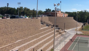
The wall builder, Decorative Paving, worked with the engineering firm of Civil Design Professionals as well as TLF Engineers to revise the wall plans and create an acceptable solution to the stability question. The solution was a seven tiered wall that utilized select backfill. The design challenge was that the excavation and geogrid layers could not extend beyond a line extending at a 1.75:1 slope away from the stadium structure footing during construction.
Additionally, for added stability, the designers had a 4 ft-6 in. deep (1.4 m) and 2 ft. (0.6 m) wide concrete shear wall constructed at the base of the slope. This concrete shear wall was designed to intercept the slip arcs that were of concern and ensure that the site remained stable while maintaining a solid construction slope.
The whole project has been a collaborative effort DePauw University, of Greencastle, Indiana, was looking for.
See here for the full project Case Study.
Global Stability Concerns
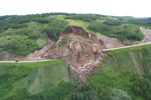
Global stability can potentially be a problem on any project and any site depending on site and soil conditions. A global stability analysis is used to determine the tendency for a slope to slide, rotate, and fail. In order for a slide to occur, something needs to change, causing an area of land that was once stable to become unstable. A very common cause for instability is the introduction of water. As in the picture, heavy rains changed the weight and internal strength of the soil until the equilibrium was lost and the slope gave way. Another common instability issue occurs when a slope is undermined, such was the possible case at the DePauw University site. Undermining can be caused naturally by erosion of the toe slope or by a contractor digging out a slope to facilitate their construction project. Understanding the site geometry and the soil condition is essential for a successful project.
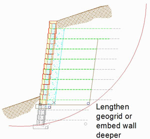
When it comes to wall designs specifically, global stability can be an issue with single or terraced walls. In a single wall, steep slopes above, below, or both should raise the stability question in the designers mind. It is not uncommon for a simple wall design project to turn into a much larger one where the site designer must redesign the slopes below and above to handle the changed geometry. For terraced wall designs, the designer must consider the orientation of the walls and design appropriate length geogrid layers to ensure stability of the final configuration. It is most common to have a larger wall below a smaller wall but if the designer designs the entire terraced wall correctly the shorter, smaller wall can support the larger upper wall. For multi-terraced walls it is common to design the length of grids for the lowest wall to be a least 60 to 70% of the total structure height (the total sum height of all terraced walls). This is a good rule of thumb to start with, but does not remove the need to analyze the structure’s global stability in a separate stability modeling program such as ReSSA.
So, what are some ways a designer can address global stability concerns when designing their retaining walls? Running a global stability analysis will determine the worst case slip arc running through the slope. To increase the stability, these slip arcs need to be pushed further into the slope to increase the safety factors. To do this, the wall designer has two typical ways to achieve this. One common way is to lengthen the geogrid layers and another way is to push the bottom of wall deeper into the foundation soils. Note that by increasing the depth of buried block you will naturally also increase the grid lengths, effectively creating a deeper, larger mass to disrupt the critical slip arcs.
To disrupt the critical slip arcs without using the wall design methods such as increasing grid length or embedding the wall deeper, the site designers can employ other methods such as the shear wall at the DePauw project. Shear walls as well as geo-piles for larger slope issues are not typically used but they can provide a unique solution for certain situations.
Another question that often comes to mind is who’s responsibility is it to verify the global stability for the wall design? Generally it is the wall designer who is expected to handle all aspects of the design, but in reality it is the geotechnical engineer who is best suited for this role. The project’s geotechnical engineer has knowledge of the site’s specific soil characteristics and a deep understanding of soil mechanics and global stability. As stated in the Best Practice for SRW Design and referenced in the NCMA Design Manual, it is often the responsibility of the geotechnical engineer to verify the global stability of the wall design.
Best Practice for SRW Design
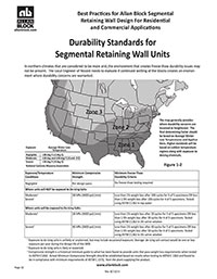
For in depth information on building and designing segmental retaining walls see Best Practices for SRW Design. Written with 12 main topics of discussion that include but are not limited to:
- Pre-Designed and Pre-Construction Considerations
- Soil Requirements
- Tall Wall Information
- Global Stability Considerations
- Freeze Thaw Durability Considerations
- References to Other Industry Related Standards
- More...
The Best Practices document was created to be used as a guide and an industry standard for any equivalent segmental retaining wall (SRW) product and not just exclusively for Allan Block products. The goal with this publication is to help drive the industry towards zero wall failures. By creating a quality set of standards it lays out a good practice for how to plan, design and build SRW walls properly.
Using this document along with the other Allan Block materials like the AB Walls Design Software and/or the AB Engineering Manual will give any engineer or design professional everything they need to properly engineer an Allan Block retaining wall. Download your copy today.
Earn Continuning Education Credits with Allan Block

Allan Block Corporation is an Accredited Provider by the International Association for Continuing Education and Training (IACET). In obtaining this accreditation, Allan Block Corporation has demonstrated that it complies with the ANSI/IACET Standards which are widely recognized internationally as standards of good practice. As a result of our Accredited Provider status, Allan Block is authorized to offer IACET CEU’s for its programs that qualify under the ANSI/IACET Standards.
Our status as an Accredited Provider of IACET CEU’s will allow us to provide engineers and others involved in retaining wall design and construction with essential credits toward renewal of their professional licensure.
See our website for all of the available courses that we offer at.

