Technical Newsletter
Issue 18
Project Information
Name: State Route 14 Freeway
Camas-Washougal, Washington
Product: AB Vertical
Size: 70,000 ft² (6,500 m²)
Local Engineer: Bill Smith
FEI Testing and Inspection Inc.
Contractor: Tapani Underground
Allan Block Manufacturer:
Oregon Block - Prineville, Oregon
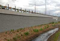
A retaining wall was needed to widen the roadway on State Route 14 between Camas and Washougal Washington
Widening a Freeway In Washington Needs Careful Thought
State Route 14 is a freeway that runs East and West along the north side of the Columbia River in Southern Washington starting in Vancouver. WSDOT called for widening of the freeway in order to improve safety, increase traffic capacity, and reduce travel time along a heavily used stretch of this road near Camas and Washougal. The project required a retaining wall with over 70,000 ft² (6,500 m²) of Allan Block Vertical retaining wall units with the tallest walls just under 30 ft (9 m) in total height. The 9 walls on the project measured just short of 1 mile (1.6 km) in length.
The Allan Block retaining wall blocks that were approved by WA State Dept. of Transportation (WSDOT) were provided by Oregon Block. Local engineer Bill Smith of FEI Testing and Inspection, provided the design along with the detailed AASHTO LRFD wall designs. The construction bid for this Design/Build project was won by Tapani Underground Inc. in part because of their status as a Certified Allan Block Contractor as well as their vast construction experience. With a Design/Build construction format the project moved along at a fast pace and FEI provided design solutions to numerous items along the way. One particular item was the multiple locations of large storm water catch basin structures located directly behind the Allan Block retaining wall.
Most of the walls were capped off with the standard WSDOT high impact crash barrier and moment slab. This meant the catch basin locations would interfere with the continuous slab. WSDOT added to the uniqueness of this detail by directing that the catch basin be completely detached from the moment slab and wall. FEI’s solution was to wrap the interrupted grid layers back similar to a reinforced slope application on the earth side of the structure. They also took advantage of Allan Block’s hollow core by turning these portions of wall into a masonry application complete with vertical rebar and fully grouted cores. This application extended a few feet to either side of the catch basin structure and fully satisfied WSDOT’s requirements.
Modifying Geogrid for Obstructions
There are several situations that can arise where the geogrid needs to be modified for a design. If the reinforcement must be partially or fully severed in the location of the obstruction, design the surrounding reinforcement layers to carry the additional load which would have been carried by the severed reinforcement.
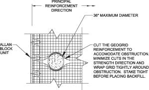
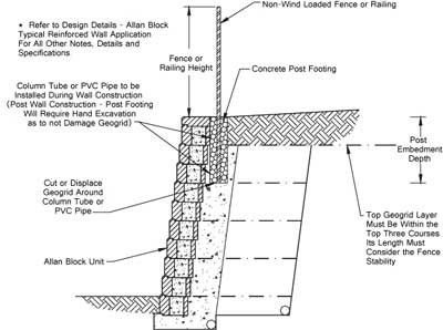
Some partial geogrid modification cases are simple obstructions like small fence posts or root balls for trees. In cases that require partial geogrid modification, it may be permissible to make a small cut in the reinforcement to accommodate the obstruction. Care should be taken to minimize the cuts in the strength direction and the geogrid should be wrapped tightly around the obstruction. Stake the grid tightly before placing any backfill (Fig 1).
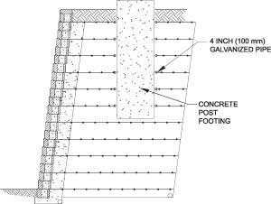
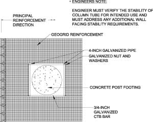
Other situations such as a large concrete post footing or storm water drop structure may require a larger grid obstruction to be incorporated. These larger structures can be accommodated for by building a frame in the geogrid around the structure to pass the loads around the structure. The frame can typically be constructed using ¾ inch galvanized continuous threaded bar on each side of the opening. The cross bars can be constructed using 4 in. (100 mm) galvanized pipe. The geogrid can be connected to the bar by either wrapping around the bar or by some means of mechanical connection (Fig 2A & 2B).
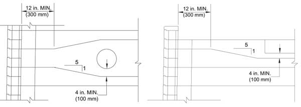
Another situation may arise with storm water drainage pipes that run parallel with the retaining wall. Occasionally these can be a reinforced concrete pipe that is larger than the geogrid space provided. In situations such as this, it is permissible to splay the geogrid around the obstruction in order to provide enough space for the obstruction. The angle of splay should not exceed 5:1 and a 4 in. minimum (100 mm) of space should be allowed between the obstruction and the geogrid (Fig 3). Also, the splay should not occur within the wall rock zone of the retaining wall.
Preventing Wall Failure
Localized top of wall overturning is typically investigated when a fence or railing is to be placed above and behind a retaining wall. In order to properly design the top of wall to resist the overturning force you need to know a few things about the wall, fence, and site conditions.
- What is the fence height and desired post spacing?
- What are the lateral loads applied to the fence?
- What type of soils are used in the retaining wall design?
- Are there any additional surcharges such as a roadway or slope above the retaining wall?
- What is the geogrid spacing and position in the top portion of the retaining wall?
Please see the Allan Block engineering manual for a full explanation of internal and external stability calculations.
Planning for Geogrid Obstructions
Fences and railings are a common sight around retaining walls. At Allan Block we are frequently asked how to properly install various fencing types along the top of our walls. This question has a variety of answers depending on the fence application. The best way to address installation of a fence is to consider the plan, design, and construction of the fence structure and the retaining wall together as one system.
A common challenge for retaining wall construction occurs when a fence is built above the retaining wall after the wall is constructed. In most cases the post footing for the fence has to be hand dug to try to mitigate damage to the geogrid. It is not recommended to use a power auger in these situations as the auger will cause a lot of damage to the geogrid and it also has the potential to pull the grid out of its intended location.
In any situation when a vertical obstruction occurs, some planning ahead can minimize the impact on the geogrid layers. Careful layout of the geogrid can allow for the obstruction to occur at a seam between geogrid rolls so that minimal cutting of the roll can be achieved. In addition, placing a sonotube footing form at the post locations during construction allows the contractor to carefully modify the geogrid. When the retaining wall is completed this allows the contractor constructing the fence to quickly and easily come and install the fence footings in the proper locations.
Tools That Make Designing and Estimating AB Projects Easy
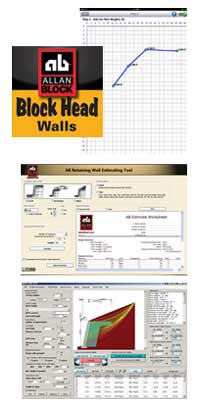
We have an app for that! Did you know that Allan Block has a huge amount of resources available to help you design your project? The AB Residential Retaining Wall Estimating App is now available on both Apple and Android tablets and phones. Use the simple screens to enter the length and height of your wall, answer questions about the layout and conditions in your yard and get a basic estimate of the blocks you will need in an easy to read format.
If you want to tackle a more detailed estimate yourself, you can download our AB Estimating Tool. The AB Estimating tool allows you to estimate any of the Allan Block product lines such as Fences, AB Courtyard, and our retaining wall collections. If you are a dealer or contractor, you can now add your own company logo and also add custom notes to the estimates.
For engineers we have AB Walls™ 10. AB Walls 10 is a comprehensive design tool which outputs professional quality construction drawings, along with the technical support data. This program allows designers to generate elevation, plan and multiple cross sectional views of their retaining wall project and transfer a conceptual layout from a site plan to a complete wall solution and then export to various CAD software programs. Additionally, its design capabilities include static and seismic calculations for internal, external and internal compound stability. AB Walls 10 can now take a designed wall project and print a complete package in one step making it an easy submittal to your client.

