AB Fence Executive Summary for Structural Testing
Experience is a valuable asset to have in virtually all aspects of design and construction. With experience comes the understanding of how concepts can become reality. But at what point do our preconceived beliefs on how things work begin to limit change and progress? Albert Einstein summarized this concept in a simple quote, "Imagination is much more important than knowledge; Knowledge is limited, Imagination encircles the world".
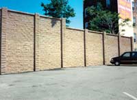
Concrete Fence Sound Barrier
Allan Block Corporation is continuing our quest to develop more efficient and dynamic building materials from the most versatile, environmentally friendly and affordable building material known to mankind - concrete. In this summary report we document how the AB Fence System performs when subjected to lateral loads, differential base support and expansive soil loading.
Fence: Product Profile
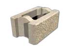
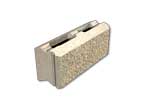
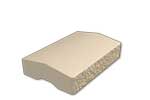
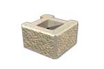
The AB Fence system combines the benefits of mortarless technology with the time proven performance of reinforced concrete. The patented ball and socket seating elements have revolutionized the process of constructing masonry structures. The three main structural components are the AB Fence Panel Block, AB Fence Post Block and the AB Fence Capstone. Together they provide the ability to design and create a fence that meets the configuration requirements of each individual project. For more information in the components of the AB Fence System, visit our Fence Product page.
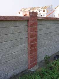
AB Fence provides the benefits of mortarless construction with the performance of reinforced concrete
Full Scale Panel and Post Testing

Research Team:
- Dr. Nigel Shrive, Department of Civil Engineering, University of Calgary
- Ryan Bakay, Department of Civil Engineering, University of Calgary
- Blair Scholelfield, Department of Civil Engineering, University of Calgary
The goal of this testing was to confirm the structural performance characteristics of the AB Fence System relative to a typical masonry design approach. Through testing we illustrate how concrete masonry structures, that vary from typical mortared structures, are able to provide benefits outside of the scope of typical masonry construction. We demonstrate how the mortarless, drystacked AB Fence system performs under loads commonly applied to fencing and sound barrier structures. The self weight of the AB Fence blocks mobilizes the ball and socket elements of the block. With the addition of self weight, the ball and socket increases the rigidity of the panel while maintaining a flexible system. This combination of flexibility and increased rigidity creates a system that absorbs a portion of the applied loads.
The post and panel configuration concept develops a structural column approach to transferring load from the panels to the columns. The columns are anchored to the ground with variable depth and diameter piles depending on the spacing between the columns, the height of the structure, the soil conditions and the loading conditions. This concept begins with basic principles used to construct masonry fences.
The results presented in this report substantiate the unparalleled performance of a concrete masonry post and panel system that is flexible and able to absorb load rather than simply transfer load. This provides the basis to use typical masonry design methods for a system that performs better than block and mortar construction. This testing also validates product specific based design methods which utilize the efficiencies of the AB Fence System.
Flexural Testing of the AB Fence System
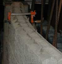
Flexural Testing
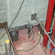
Displacement Transducers Measuring Rotation
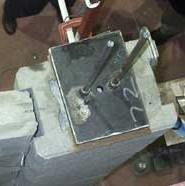
Post-Tensioned Masonry Posts
Test Objective:
"Prove the load carrying capabilities of the AB Fence panel sections under extreme sustained lateral loads." Three different design configurations were used to allow for multiple conditions to gain a better understanding of how the panel assemblies handle lateral loads and how load is transferred to the AB Fence Post. The overall objective was to provide test results that confirm the unique qualities of the mortarless ball and socket configuration of the AB Fence Panel Block and its interface to AB Fence Post structure.
Facilities & Test Apparatus
Testing was performed at the University of Calgary in the structures labs at the Civil Engineering Building and the Calgary Centre for Innovative Technology. AB Fence Panel and Post units were produced and supplied by CCI Industries per the Allan Block specifications and ASTM C1372 unit requirements.
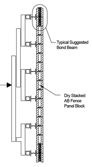
The frame used for testing was a simple portal frame constructed out of three W1000X222. The height of the frame was 5.5 m and the width was 4 m. The load distribution system is shown in Figure 1. A series of simply supported spreader beams was designed to distribute a point load applied at the back of the system into a series of equally spaced point loads. The actuator used to apply the single point load has a maximum capacity of 50 kN. A steel channel was used to provide a level surface to place the first course of panel block on Structure A and Structure B. On Structure C, a crushed rock base was used as the leveling surface.
Displacement transducers were placed at the columns and the middle of the panel assembly. Transducers of different capacities were used to measure the deflection of the different setups, based on expected results from each.
Column structures are typically constructed by setting post blocks on a predetermined pile, reinforced with rebar, which ties the column structure together. The predetermined size of the below grade pile is developed to prevent permanent movement of the column structure during maximum loading conditions. To simulate the field column structures, posts were stacked and grouted with sleeves in the center grout area. These sleeves allowed for attachment and subsequent post-tensioning of the post assembly to the steel channel on which the wall was constructed. This ensured that the panel and post would behave in a manner typical to what would be experienced in the field. A 30 MPa grout was used in the post assemblies.
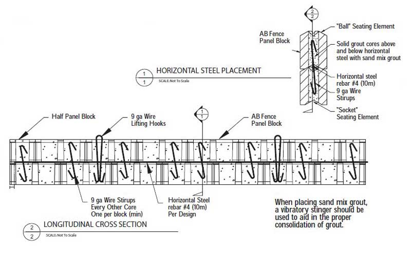
Suggested Bond Beam Assembly Details
Test Setup

Fence Top Bond Beam (Structure A)

Fence Top Bond Beam Deflection (Structure A)
Flexural Test Setup A:
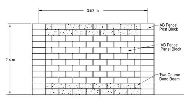
Structure A was constructed with a panel length of seven blocks (3.13 m) and a height of twelve blocks(2.44 m). Including post blocks, the center to center spacing of the post and panel configuration was 3.53 m. Two bond beams were incorporated into the panel assembly consisting of the bottom two courses and the top two courses of the AB Fence panel. Each bond beam utilized a 15-M rebar and was filled with a 37.5 MPa grout with a maximum aggregate size of 10 mm. Stirrups were not incorporated into bond beams used on Structure A.
This bond beam configuration simulated the worst-case scenario of maximum rebar size, lack of stirrups and large aggregate grout. Observation during construction confirmed the difficulty of proper coverage of the rebar and poor grout consolidation throughout the cores and openings. These observations confirmed that adequate coverage is not possible using a 15-M rebar and large aggregate grout. The test on this structure was performed in a condition that simulated a less than desirable final construction assembly. Structure A replicated a typical design configuration for a structure of this height, with the exception of the make up of bond beams.
Flexural Test Setup B:

Assembled 17 Course Block Fence (Structure B)
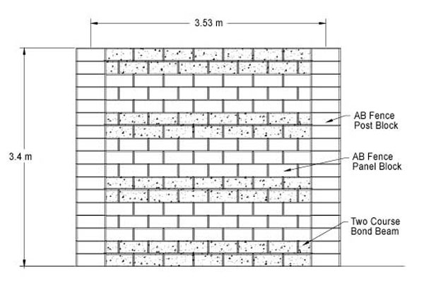
Structure B was constructed with a panel length of seven blocks (3.13 m) and a height of 17 blocks (3.4 m). Including post blocks the center-to-center spacing of the post and panel configuration was 3.53 m. Four bond beams were incorporated into the panel assembly consisting of the bottom two courses, the 6th and 7th, the 11th and 12th, and the top two courses of the AB Fence panel.
With the exception of the first bond beam course, which was left in place from Structure A, the three additional bond beams were constructed with a typical sand grout mix which yielded a 28 day compressive strength of 28.7 MPa. This grout mix complied with the existing Allan Block recommendations for bond beam construction for on site installations. Stirrups were not used in the bond beams. Structure B was constructed to replicate an actual panel section as designed for a City of Calgary project. An additional bond beam was used in this design when compared to a design of a typical masonry fence.
Flexural Test Setup C:
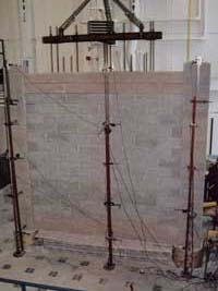
Flexural Test (Structure C)
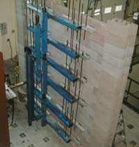
2 Bond Beams and 13 Dry-Stacked Courses (Structure C)
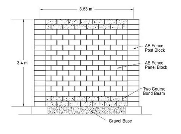
Structure C was constructed with a panel length of seven blocks (3.13 m) and a height of 17 blocks (3.4 m). Including post blocks the center to center spacing of the post and panel configuration was 3.53 m. Two bond beams, constructed per the Suggested Bond Beam Assembly Detail, were incorporated into the panel assembly. The bond beams were located at the bottom two courses and the top two courses of the AB Fence panel.
Each bond beam utilized a 10-M rebar, filled with 28 MPa sand grout, with stirrups placed in every other core. Structure C was first built to a height of 3 m and used in the free-span test and frost heave test, prior to being constructed to full height and exposed to the lateral load test. The bottom bond beam rested on the piles at both ends and a gravel base that was placed after completion of the free-span and frost heave testing.
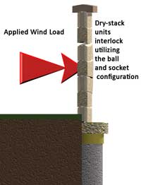
Dry-stack units interlock utilizing the ball and socket configuration
Test Procedures
To simulate a sustained wind load, a load spreading system was positioned on one side of the AB Fence panels. On the other side of the panel, deflection gauges were placed at one-meter vertical intervals and one-meter horizontal intervals. A horizontal applied load from a hydraulic ram was applied to the fence with the load spreading system. Deflection readings were taken as the forces were applied. Strain gauges were attached to the rebar in the bond beam to measure how much load was being transmitted to the bond beam reinforcement. This also provided information to derive how much load was absorbed by the ball and socket connection, which is integral to the panel block assemblies.
Incremental forces were applied and recorded to provide documentation of unfactored wind loads at 97 km/h through 386 km/h in increments of 16 km/h. The total time elapsed for the sustained load was recorded as well as the time at each increment prior to increasing the load. Deflection readings at the panel and the posts were recorded at each incremental load.
At completion of the test, the load was removed and the permanent deflection was recorded.
Testing Summary
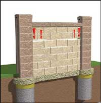
In order for bulging to occur in the panel, the locking forces within the ball and socket joint of the dry-stacked units must literally lift the courses of block above the bulge. The self weight of these courses enhances the strength and rigidity of the panel and continues to increase as you move lower in the panel
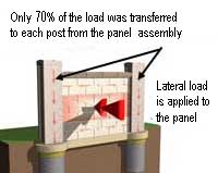
Due to the rigidity and flexibility of the panel created by the ball and socket configuration, the panel absorbed 30% of lateral loads
Structure A and Structure B performed at levels that far exceeded calculated expectations. Design calculations were based on wind loading of 129 km/h. At these levels the system would have been acceptable and the design calculations exhibited a system that would perform well. Structure A began to exhibit failure at 193 km/h. This test helped prove the performance of the panel assembly, with bond beams at the top and bottom, with results that exceeded design expectations by 50%.
Structure B employed bond beams every 1 m and calculations illustrated that with nominal strengths, failure should have occurred at a wind loading of just over 200 km/h. Testing proved that the system had far greater structural stability as the sustained load was taken to 386 km/h without failure.
Structure C illustrated that a 3.4 m high fence with bond beams at the top and bottom only, could withstand wind loads in excess of 175 km/h. Calculations based on standard practices for masonry design would have anticipated failure in the bond beams at 110 km/hr. With thirteen un-reinforced dry stacked courses the inherent strength of the ball and socket was clearly demonstrated. The stroke of the cylinder used to apply the load to the AB Fence panel assembly was exceeded, which terminated the test prior to failure being experienced. The maximum deflection occurred at approximately 2.5 m above the base and was recorded to be just over 50mm.
These tests illustrated the inherent ability of the ball and socket configuration of the panel block to add rigidity to the wall and absorb applied loads in the process. As higher loads were applied, panel flexing occurred which highlighted the dynamic characteristics of the AB Fence System. It should also be noted that the panel blocks actually absorbed a portion of the applied load. Preliminary indications show that a reduction of 30 percent would be appropriate based on the performance of the assembly and the recorded loads. An interesting commentary on the performance may be drawn from the fact that the maximum recorded wind speed in the Province of Alberta is approximately 130 km/h. This is another indicator that current masonry design procedures are extremely conservative and the combination of built in rigidity and flexibility of the AB Fence may be used to develop more efficient and cost effective designs.
Concrete Fence Panel Free Span
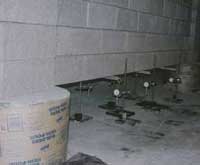
Panel Free Span Testing
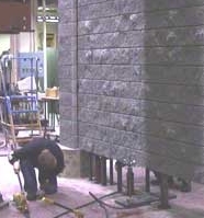
Assembled Block Fence
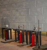
Hydraulic Jacks
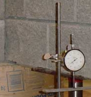
Dial Gauges for Measuring Deflection
Test Objective:
"Prove the load carrying capabilities of a panel assembly that is simply supported by the panels resting on simulated piles at the posts." With different grade beam designs determine the effectiveness of each, and any limitations in clear span applications. This would simulate the worst-case conditions for differential settlement and substantiate the performance in this scenario.
Facilities & Test Apparatus
Testing was performed at the University of Calgary in the structures labs at the Civil Engineering Building and the Calgary Centre for Innovative Technology. AB Fence Panel and Post units were produced and supplied by CCI Industries per the Allan Block specifications and ASTM C1372 unit requirements.
Test Setup
Three different structures were built to conduct these tests. Each structure had a different bond beam configuration to determine the suitability of each in actual field applications. The three structures were constructed with a panel length of seven blocks (3.13 m) and a height of 15 blocks (3 m). Including post blocks the center-to-center spacing of the post and panel configuration was 3.53 m. Bond beams were located at the bottom, center and top of the panel assembly for the first two structures.
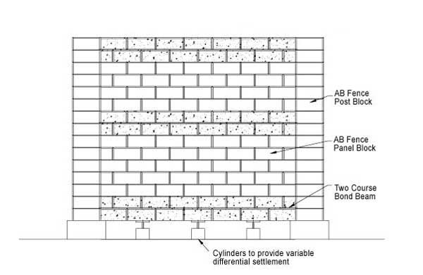
Panel Free Span
Structure One was constructed with a bottom two course bond beam with a 15M bar and no stirrups using a sand grout mix. Structure Two consisted of a single course lintel style bond beam with a 15M bar using a sand grout mix. Structure Three was constructed following the Suggested Bond Beam Assembly Detail. Pile caps were constructed above floor level and attached to the floor, using 50 mm in diameter high strength DYWIDAG Threadbar® prestressing tendon. Sono-tube forms were used and reinforcement was included, which protruded from the top of the pile. The reinforcement for the AB Fence post columns was tied to the protruding pile reinforcement to provide anchorage and increase the interaction between the column and pier. Columns were reinforced with four 10-M bars and grouted with a sand grout mix. Four additional supports were located beneath the panel block to provide temporary support until the commencement of the testing. Once the wall was constructed and cured, the legs of each support were replaced with hydraulic jacks and steel plates. Wall deflections were measured using dial gauges at six locations, three on each face of the bottom of the panel assembly.
Test Procedures
To simulate a complete free span condition of the panel assemblies, that are simply supported by piles on both ends, the temporary supports were removed. Deflection was recorded after the removal of all supports.
Testing Summary
No damage at any stage occurred while the supports were being lowered to simulate a panel simply supported by the piles. The three different bond beam assemblies were able to support the full weight of the panel assembly with a deflection of less than 0.5 mm.
Frost Heave or Ground Swelling Testing
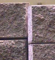
Fence panel movement under frost heave loading
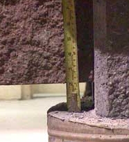
Fence panel movement under frost heave loading
Test Objective:
"Establish the ability of the post and panel structure to handle loads exerted on the panels from the underside of the panel." The ability of the AB Fence Panel assembly to bear on a thin gravel footing just below grade level is an inherent positive feature of the system and this test verified the ability of the system to perform under adverse conditions. These types of loads may be experienced when the ground swells from frost or expansive soils.
Facilities & Test Apparatus
The same facility and apparatus were used for this test as were used in the Panel Free Span Test.
Test Setup
The same test setup was used for this test as were used in the Panel Free Span Test.
Test Procedures
Upon completion of the Concrete Fence Panel Free Span test, floor supports were repositioned to establish a level ground condition. To simulate the effects of localized frost heave, loads were applied at three locations, the ¼ panel mark, ½ panel mark and ¾ panel mark. Loading was accomplished by using a jack that was pushing on a steel plate measuring 150 mm by 450 mm located below the bond beam. Starting with the right side, the jack was engaged to apply a load of 30 kN, while the other panel marks were simply supported simulating stable subgrade. A deflection reading was recorded to document the movement associated with a 30 kN ground movement load. The panel was lowered to its starting position. The test was conducted again in the mid point of the bond beam and on the opposite side at the ¾ panel length mark. This procedure provides performance information for differential ground heave conditions within one panel assembly.
Testing Summary
Structure One illustrated that localized failure would occur when large rebar was used and stirrups were not incorporated into the bond beams. No damage occurred at any stage with either the Structure Two or Three bond beam assemblies during simulated frost heave conditions. The 30kN load was reached in both cases with a deflection of nearly 75 mm. Bond beams for Structures Two and Three were designed to assume that they would be constructed on soft soil and therefore required to handle extreme loads in localized areas on the panel assembly. The combination of the Panel Free Span and Frost Heave testing illustrated that the two course bond beam with stirrups performed at the same level as a conventional masonry lintel bond beam.
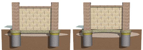
Flexibility during frost heave: The bottom two-course bond beam provides the support to the panel and allows the system to move when the underlying soils expand and contract.

