Technical Newsletter
Issue 19
Project Information
Name:Townelake Developments
Product:AB Classic
Size: 60,000 ft² (5,575 m²)
Local Engineer: Converse Consultants
Contractor: Earth Management
Allan Block Manufacturer:Clayton Block
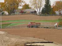
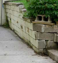

Liquid Limit Test
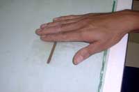
Plastic Limit Test
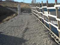
Using select backfill during wall construction
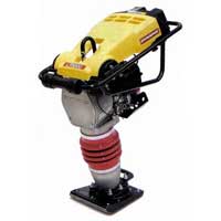
Jumping Jack Tamper
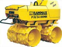
Walk Behind Roller
Townelake Has No Problems Dealing With Poor Soil
The benefits for the Townelake development were enormous. Its location put the homeowners at the center of a commuter’s dream since it was close by to the Garden State Parkway and several major commuting routes as well as commuting bus and train lines. However, the site that was developed had its challenges that needed to be addressed.
The site used to belong to Sayre & Fisher Brick Company. They manufactured clay brick at that location because of the different clay deposits known throughout that region. These clay soils created problems with the future development of the site since existing slopes were already failing. However, the location of the site being a "commuter’s dream" could not be overlooked by the developer, Kaplan Companies.
With the professional services of a local engineer, Converse Consultants and an AB Master Wall Builder, Earth Management working together, this site full of clay started to take shape. Design and construction activities had to adapt with the different soils and slopes encountered at the site.
- The Eastern portion of the development had clay soils that were not acceptable for retaining wall construction and select engineered backfill had to be brought in to replace the clay.
- In other areas, the clay soils could be used as backfill but the design had to incorporate longer geogrid lengths and higher strength geogrid layers to accommodate the additional pressure exerted on the wall.
- The terraced retaining wall structures along the Northern side of the property had to be engineered to stabilize the existing slope and ensure global stability. Large shot-rock material from a local quarry was placed under the retaining walls to work as a key and prevent future landslides.
- Throughout the site, water was properly managed by installing chimney and blanket drains in the walls to handle the elevated groundwater levels. Final grading made sure that water was diverted around the retaining walls and were collected appropriately
Proper design and construction of over 60,000 square feet of Allan Block retaining walls utilizing the AB Stones product from Clayton Block allowed for the construction of 225 beautiful Colonial design single family homes on this challenging site. A second phase is now in the works with an additional 30,000 square feet of retaining wall. With the proper game plan, there is no reason to believe that this project will be nothing but a success as well.
Identifying Clay Soil
One of the first things that needs to be identified when designing or building a retaining wall is what are the soil conditions on the site. Most of us have had the experience of working with clay soils, which means that we know there are a few things to worry about. However, the flexible nature of Allan Block retaining walls provide a huge advantage since one of the critical design aspects when working with clay soil is adjusting for the additional movement.
Cast in place or masonry block retaining walls and foundation and basement walls can experience cracking during the first year due to moisture changes in the clay soil. Expansive soil will move as moisture in the soil changes. During wetter seasons clay grows, during dry seasons clay shrinks. The expansive soil will exert more pressure on the retaining wall and cause the movement.
Atterberg Limits

Atterberg Limits – Stages of Consistency for Soil
In order to determine the potential expansion of clay soil they are often tested to determine their "plasticity index". The plasticity index is a measure of the range over which the clay sample will retain its plastic or "moldable" characteristics. As water is added to clay, it will cease to behave like a solid and start behaving like a plastic. The percentage of water at that point is the plastic limit (PL). If additional water is added to the soil to the point where the sample stops behaving like a plastic, but more like liquid, that point is called the liquid limit (LL).
The plastic and liquid limits of the soil are often referred to as the Atterberg Limits after the scientist that defined them. Knowing the Atterberg Limits of the soil will help determine how that soil may behave. Any clay that has a plasticity index (PI = LL - PL) of 50 or greater is considered to be highly plastic and are commonly referred to as “fat clays”. The problem with fat clays is that they can be very expansive and cause problems behind retaining walls. Allan Block recommends that any soils that have a plasticity index (PI) > 20 or a liquid limit (LL) > 40 should not be used in wall construction.
Understanding the type of clay soil you have on a job site is imperative. Using expansive clays in wall construction will only lead to future problems.
Working with Clays
Expansive clays can cause very high lateral pressures on the back of a retaining wall structure and should be avoided whenever possible. The previous article talked about the different laboratory tests that can be conducted to determine the expansion potential so that the design can accommodate the additional pressures. Alternatively, one of the following measure could be employed:
There are expansive soil chemical treatments that are designed to reduce the expansion potential. More often than not, lime is used to eliminate the swelling potential. However, not all soil will work well with lime so testing is being done by highway departments on silica fume, fly ash and different polymers, acids and emulsions.
Construction activities have included pre-wetting the clay prior to building the retaining wall. The idea is to cause pre-expansion of the soil so that further expansion pressure will be minimal. This is done more often in the foundation soils and not in the soils behind the retaining wall.
The most common approach is to remove the expansive clay and replace it with select engineered backfill. This material will drain the water away from the expansive soil and act as a buffer zone between the expansive clay and the retaining wall.
Proper Compaction
Moisture Content is Critical
The most economical means of mitigating problems associated with expansive clays is proper compaction of the soils at the appropriate moisture content. Experience and research has shown that compacting expansive soils at moisture contents that exceed the AASHTO T99 and ASTM D698 optimum will result in less water absorption and provide a slightly higher strength when compared to soils that were compacted dry of optimum moisture.
Use the Right Equipment
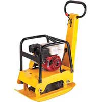
Walk Behind Plate Compactpor
The desired level of compaction is best achieved by matching the soil type with the compaction method. Granular soils are not cohesive and require a shaking or vibrating action to move them. Therefore, vibratory plate compactors.
Cohesive and expansive clays have particles that stick together. Therefore, a machine with a high impact force is required to ram the soil and force the air out to arrange the soil particles. A rammer works well but is not the best machine to use behind a retaining wall since you might move the block out of position and level. The better piece of equipment is a pad-foot vibratory roller which will provide a higher production.
Allan Block recommends using the vibratory plate compactor on top of the retaining wall and in the granular material behind the retaining wall, but switching to the pad-foot vibratory roller if clays are being used in the backfill area.


