Technical Newsletter
Issue 17
Typical Section
Lighting

AB Walls Design Output
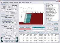
AB Walls Design Output
Wall Penetrations for Retaining Walls
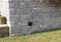
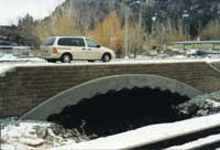
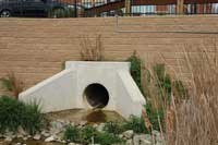
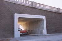
The unparalleled use of segmental retaining walls (SRW) around the world has brought design ideas as widely varied as one can imagine. With varied project applications comes the need for various types of wall openings. They come in every shape and size imaginable. The most common would be the simple drain pipe opening. The most complex might be a large corrugated steel bridge culvert. Most openings are for allowing water to flow from behind the wall. Others openings allow ventilation from buildings or traffic to flow through as a bridge or common utilities.
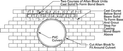
Any type of opening requires two things, to be sized appropriately for the intended use and to provide support for the surrounding wall structure. Support can be provided with no external assistance for small pipes by simply cutting the wall facing to fit the opening. For larger openings, stability can be maintained by building supporting bond beams directly into the wall facing or by a fully reinforced concrete headwalls for larger openings. The purpose of either type of external assistance is to add stability into the wall as well as into the pipe structure. Engineers and site designers need to first design the pipe for the desired capacity and then based on the opening size the type of wall opening can be determined and designed.
For many large structure type openings, differential settlements need to be addressed. These structures are typically built on frost footings but the walls are not. Therefore the designer must determine if additional foundation soil stabilization is required prior to wall construction. Minimizing differential settlements will minimize stress cracks in the face adjacent to the fixed structure. Installation of vertical control joints may also be required.
Design & Construction Tips for Culverts/Openings in Allan Block Retaining Walls
Design of a wall penetration will depend on the use and size of the opening. For large bridge structures the weight of the retaining wall is built into the overall capacity of the bridge structure so the designer may only need to design for the sliding or shear along the surface and edge of the bridge culvert. This is accomplished by adding a concrete lip or beauty ring around the culvert structure.The concrete lip is formed and cast between the culvert edge and the face of the Allan Block units.
Typically the lip will have mild steel bars along with anchoring devices allowing attachment to the culvert. Anchoring methods will vary depending on the material of the pipe or culvert (typically concrete, corrugated steel, HDPE, etc.). Other openings may require fully reinforced concrete headwalls built with a structural footing such as a box culvert bridge.
Immovable structures such as these will benefit from vertical control joints saw cut into the block facing. Control joints help to control potential surface cracking caused by differential settlements between the fixed headwall and flexible wall system. Control joints can be saw cut into the facing as the wall is being constructed by cutting every other course of block. For the other courses, the joints are naturally formed by the block joints.
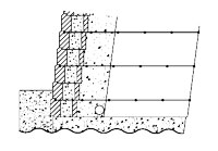
For pipes carrying water, the designer should have additional drainage rock placed around the pipe in the reinforced zone behind the wall facing. This additional washed rock will allow water that may leak from the pipe over time to evacuate from the wall’s backfill. If additional drainage rock is not used and the pipe leaks, the unintended water flow could cause serious internal damage to the wall system. Additionally, for pipes that carry flowing water, the designer must evaluate the outflow and use rip-rap or other surfacing material in front of the wall for erosion control.
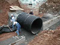
Working with rigid structures like box culverts can be very straightforward because the structure itself will not flex. However, working with flexible corrugated steel culverts can be a construction challenge.
These structures tend to deform slightly if not built in a methodical and symmetrical manner. The contractor should construct a course at a time simultaneously on both sides of the culvert. This way, any deformations in the culvert are symmetrical allowing the course positions to be the same on both sides.
When working with a concrete headwall, the headwall is typically not cast to its full height during the first pour. A final pour is made once the Allan Block wall is built up on each side. This way the final concrete pour can be placed to match the exact height of the adjacent block course so subsequent courses can be placed directly on top of the final headwall pour. Any required beauty ring casting will follow near the end of wall construction.
Construction of any wall project requires planning and will vary for each type. For larger openings there are most likely multiple contractors involved, one installing the pipe and headway and another installing the wall. Use the preconstruction meeting to plan the sequencing of construction. Knowing what is expected prior to starting work will produce a successful project.
Don’t Forget About Lighting
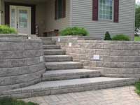
Surface mounted lighting and other low voltage equipment will require wall penetrations for mounting the fixture and installing the wires and conduit. A detailed plan should be thought through prior to any wall construction as conduits, wires and access boxes may need to be installed during construction.
AB Walls 10 Elevation Views and Estimating
AB Walls 10 is Allan Block’s SRW design software. It allows the designer to not just design a simple cross section like most programs but has many valuable features including the ability to layout detailed elevation and plan views, cut multiple design cross section along the length of the wall, export all design drawings to a DXF format for uses in any CAD program. Along with many other design and detailing function, the program is capable of providing a detailed set of material quantities including everything required to build the project.
AB Walls 10 is available through your local Allan Block producer or by contacting the Allan Block Engineering Department.
DID YOU KNOW:
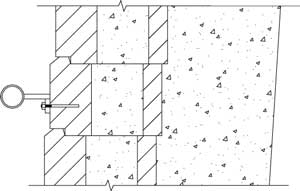
Anchoring signage, handrails or equipment to the Allan Block facing can also be considered a wall penetration as well. Typical masonry concrete anchoring bolts can be used in the facing. The designer should size the anchoring bolt for the project. Larger anchoring needs will require greater consideration from the engineer.

